Although there are many programs for ventilation calculations, many parameters are still determined in the old fashioned way, using formulas. The calculation of the load on ventilation, area, power and parameters of individual elements is carried out after drawing up a diagram and distributing equipment.
This is a difficult task that only professionals can do. But if you need to calculate the area of some ventilation elements or the cross-section of air ducts for a small cottage, you can really handle it yourself.
Calculation of air exchange
If there is no toxic discharge in the room or their volume is within acceptable limits, air exchange or ventilation load is calculated by the formula:
R=n * R1,
hereR1 - the need for air of one employee, in cubic meters / hour,n - the number of permanent employees in the premises.
If the volume of the room for one employee is more than 40 cubic meters and natural ventilation works, there is no need to calculate air exchange.
For household, sanitary and utility rooms, ventilation is calculated based on hazards based on the approved air exchange rate:
- for office buildings (hood) - 1.5;
- halls (feed) - 2;
- conference rooms for up to 100 people with a capacity (for serving and exhausting) - 3;
- rest rooms: supply 5, extract 4.
For industrial premises in which hazardous substances are constantly or periodically emitted into the air, ventilation is calculated based on hazards.
Air exchange for hazards (vapors and gases) is determined by the formula:
Q=K\(k2-k1),
hereTO - the amount of steam or gas appearing in the building, in mg / h,k2 - the content of steam or gas in the outflow, usually the value is equal to the MPC,k1 - content of gas or steam in the supply.
The concentration of harmful substances in the inflow is allowed up to 1/3 of the MPC.
For rooms with the release of excess heat, air exchange is calculated using the formula:
Q=Ghutc(tyx — tn),
hereGizb - excess heat drawn to the outside, measured in watts,from - specific heat capacity by mass, s = 1 kJ,tyx - the temperature of the air removed from the room,tn - supply temperature.
Heat load calculation
The calculation of the heat load on ventilation is carried out according to the formula:
Qin = Vn * k * p * CR(text - tnro),
in the formula for calculating the heat load on ventilationVн - the external volume of the building in cubic meters,k - the frequency of air exchange,tvn - the temperature in the building is average, in degrees Celsius,tnro - outdoor air temperature used for heating calculations, in degrees Celsius,R - air density, in kg / cubic meter,Wed - heat capacity of air, in kJ / cubic meter Celsius.
If the air temperature is lower tnro the frequency of air exchange decreases, and the heat consumption indicator is considered equal Qw, constant.
If, when calculating the heat load on ventilation, it is impossible to reduce the air exchange rate, the heat consumption is calculated from the heating temperature.
Heat consumption for ventilation
The specific annual heat consumption for ventilation is calculated as follows:
Q = [Qo - (Qb + Qs) * n * E] * b * (1-E),
in the formula for calculating the heat consumption for ventilationQo - total heat loss of the building during the heating season,Qb - household heat input,Qs - incoming heat from outside (sun),n - coefficient of thermal inertia of walls and floors,E - reduction factor. For individual heating systems 0,15, for central 0,1, b - heat loss coefficient:
- 1,11 - for tower structures;
- 1,13 - for multi-section and multi-entrance buildings;
- 1,07 - for buildings with warm attics and basements.
Calculation of the diameter of the ducts
The diameters and cross-sections of ventilation ducts are calculated after a general system diagram has been drawn up. When calculating the diameters of ventilation ducts, the following indicators are taken into account:
- Air volume (supply or exhaust), which must pass through the pipe for a given period of time, cubic meters \ h;
- Air speed. If, when calculating ventilation pipes, the flow rate is underestimated, air ducts of too large a cross-section will be installed, which entails additional costs. Overestimated speed leads to vibrations, increased aerodynamic hum and increased equipment power. The speed of movement on the tributary is 1.5 - 8 m / s, it varies depending on the site;
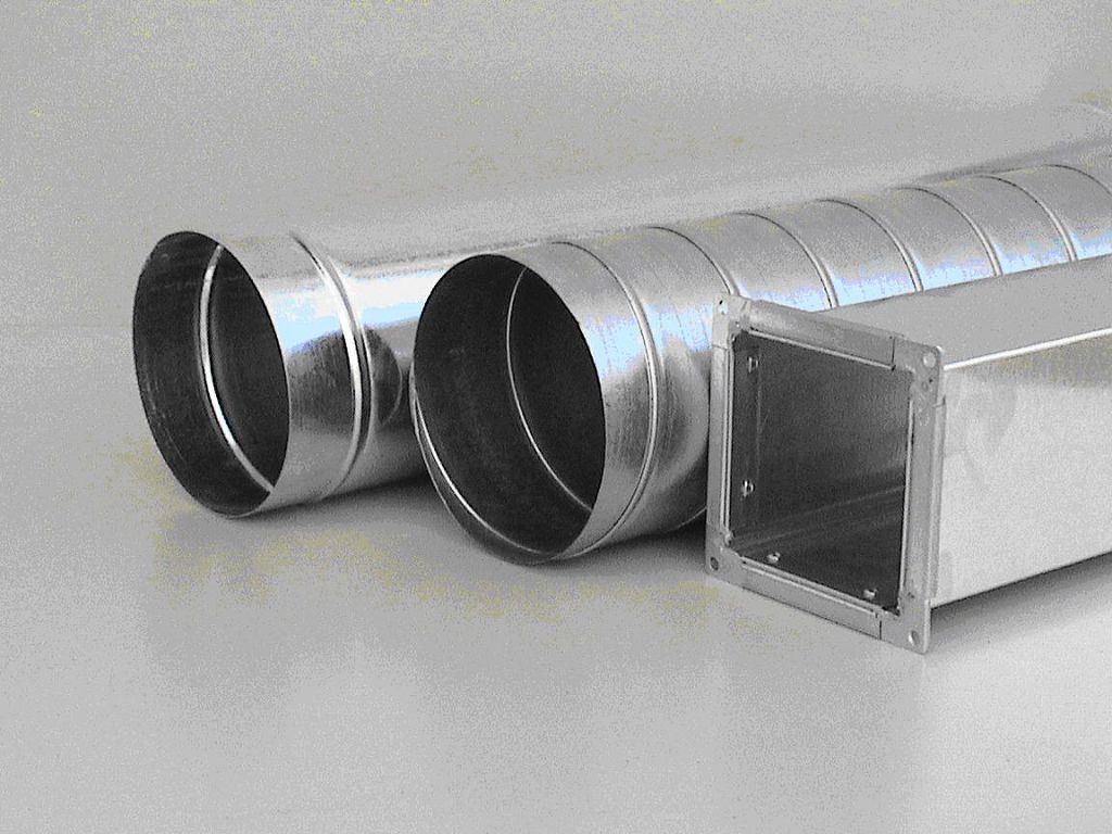
- Ventilation pipe material. When calculating the diameter, this indicator affects the wall resistance. For example, rough-walled black steel has the highest resistance. Therefore, the estimated diameter of the ventilation duct will have to be slightly increased in comparison with the norms for plastic or stainless steel.
| Plot type | Flow rate, m / s |
| Main pipelines | 6 to 8 |
| Side layering | 4 to 5 |
| Distribution pipelines | 1.5 to 2 |
| Top inflows | 1 to 3 |
| Hoods | 1.5 to 3 |
Table 1... Optimum air flow rate in ventilation pipes.
When the throughput of future air ducts is known, the cross-section of the ventilation duct can be calculated:
S=R\3600v,
herev - the speed of the air flow, in m / s,R - air consumption, cubic meters \ h.
The number 3600 is a time factor.
Knowing the cross-sectional area, you can calculate the diameter of the circular ventilation duct:
here:D - the diameter of the ventilation pipe, m.
If it is necessary to calculate the diameter of a rectangular ventilation pipe, its indicators are selected based on the obtained cross-sectional area of the round pipe.
Calculation of the area of ventilation elements
The calculation of the ventilation area is necessary when the elements are made of sheet metal and it is necessary to determine the quantity and cost of the material.
The ventilation area is calculated by electronic calculators or special programs, many of them can be found on the Internet.
We will give several tabular values of the most popular ventilation elements.
| Diameter, mm | Length, m | |||
| 1 | 1,5 | 2 | 2,5 | |
| 100 | 0,3 | 0,5 | 0,6 | 0,8 |
| 125 | 0,4 | 0,6 | 0,8 | 1 |
| 160 | 0,5 | 0,8 | 1 | 1,3 |
| 200 | 0,6 | 0,9 | 1,3 | 1,6 |
| 250 | 0,8 | 1,2 | 1,6 | 2 |
| 280 | 0,9 | 1,3 | 1,8 | 2,2 |
| 315 | 1 | 1,5 | 2 | 2,5 |
table 2... The area of straight round ducts.
The value of the area in sq. M. at the intersection of horizontal and vertical lines.
| Diameter, mm | Angle, hail | ||||
| 15 | 30 | 45 | 60 | 90 | |
| 100 | 0,04 | 0,05 | 0,06 | 0,06 | 0,08 |
| 125 | 0,05 | 0,06 | 0,08 | 0,09 | 0,12 |
| 160 | 0,07 | 0,09 | 0,11 | 0,13 | 0,18 |
| 200 | 0,1 | 0,13 | 0,16 | 0,19 | 0,26 |
| 250 | 0,13 | 0,18 | 0,23 | 0,28 | 0,39 |
| 280 | 0,15 | 0,22 | 0,28 | 0,35 | 0,47 |
| 315 | 0,18 | 0,26 | 0,34 | 0,42 | 0,59 |
Table 3... Calculation of the area of bends and semi-bends of a circular cross-section.
Calculation of diffusers and grilles
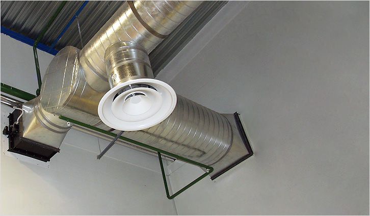
Diffusers are used to supply or remove air from a room. The cleanliness and air temperature in every corner of the room depends on the correct calculation of the number and location of ventilation diffusers. If you install more diffusers, the pressure in the system will increase and the speed will decrease.
The number of ventilation diffusers is calculated as follows:
N=R\(2820 * v * D * D),
hereR - throughput, in cubic meters \ hour,v - air speed, m / s,D - diameter of one diffuser in meters.
The number of ventilation grilles can be calculated using the formula:
N=R\(3600 * v * S),
hereR - air consumption in cubic meters \ hour,v - air speed in the system, m / s,S - cross-sectional area of one lattice, sq.m.
Duct heater calculation
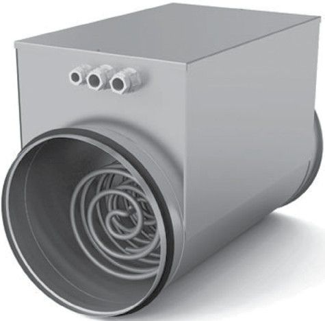
The calculation of an electric type ventilation air heater is made as follows:
P=v * 0,36 * ∆T
herev - the volume of air passed through the air heater in cubic meters / hour,∆T - the difference between the outside and inside air temperature, which must be provided to the heater.
This figure varies within 10 - 20, the exact figure is set by the client.
The calculation of the ventilation heater begins with the calculation of the frontal cross-sectional area:
Af =R * p\3600 * Vp,
hereR - volume of inflow flow rate, cub.m. \ h,p - density of atmospheric air, kg \ cubic meter,Vp - mass air velocity at the site.
The section size is required to determine the dimensions of the ventilation heater. If, according to the calculation, the cross-sectional area turns out to be too large, it is necessary to consider an option from a cascade of heat exchangers with a total calculated area.
The mass velocity index is determined through the frontal area of the heat exchangers:
Vp=R * p\3600 * Af.fact
For further calculation of the ventilation air heater, we determine the amount of heat required to heat the air flow:
Q=0,278 * W * c (TP-Ty),
hereW - warm air consumption, kg / hour,TP - supply air temperature, degrees Celsius,Tu - outdoor air temperature, degrees Celsius,c - specific heat capacity of air, constant 1.005.
Since in supply systems the fans are placed in front of the heat exchanger, the flow rate of warm air is calculated as follows:
W=R * p
When calculating the ventilation heater, the heating surface should be determined:
Apn = 1.2Q\k(Ts.t-Ts.v),
herek - coefficient of heat output by the heater,Tc.t - the average temperature of the coolant, in degrees Celsius,Tc.w - average supply temperature,1,2 Is the cooling coefficient.
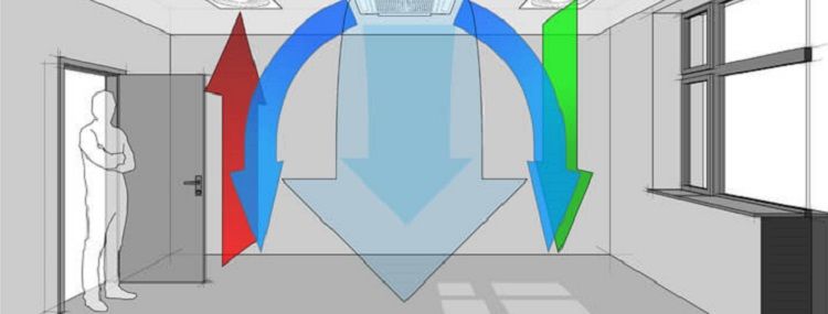
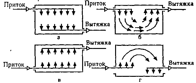
Displacement ventilation calculation
With displacement ventilation, calculated ascending air currents are installed in the room in places of increased heat generation. Cool clean air is supplied from below, which gradually rises and in the upper part of the room is removed to the outside along with excess heat or moisture.
When properly calculated, displacement ventilation is much more efficient than mixing in the following types of rooms:
- halls for visitors in catering establishments;
- conference rooms;
- any halls with high ceilings;
- student audiences.
The calculated ventilation displaces less efficiently if:
- ceilings below 2m 30 cm;
- the main problem of the room is the increased generation of heat;
- it is necessary to lower the temperature in rooms with low ceilings;
- powerful turbulence in the hall;
- the temperature of hazards is lower than the air temperature in the room.
Displacement ventilation is calculated based on the fact that the thermal load on the room is 65 - 70 W / m2, with a flow rate of up to 50 liters per cubic meter of air per hour. When the heat loads are higher and the flow rate is lower, it is necessary to organize a mixing system combined with cooling from above.
The video will tell you about the compact displacement ventilation unit: